Charger Circuit
RP2040 - ESP32C3 Development Board supports on board charging for a single cell 3.7V Li-on based battery.
The battery on the development board can be charged using the USB-C connector. The circuit handles the power switch automatically from battery to USB-C when USB connector is plugged.
Battery Connection & Protection
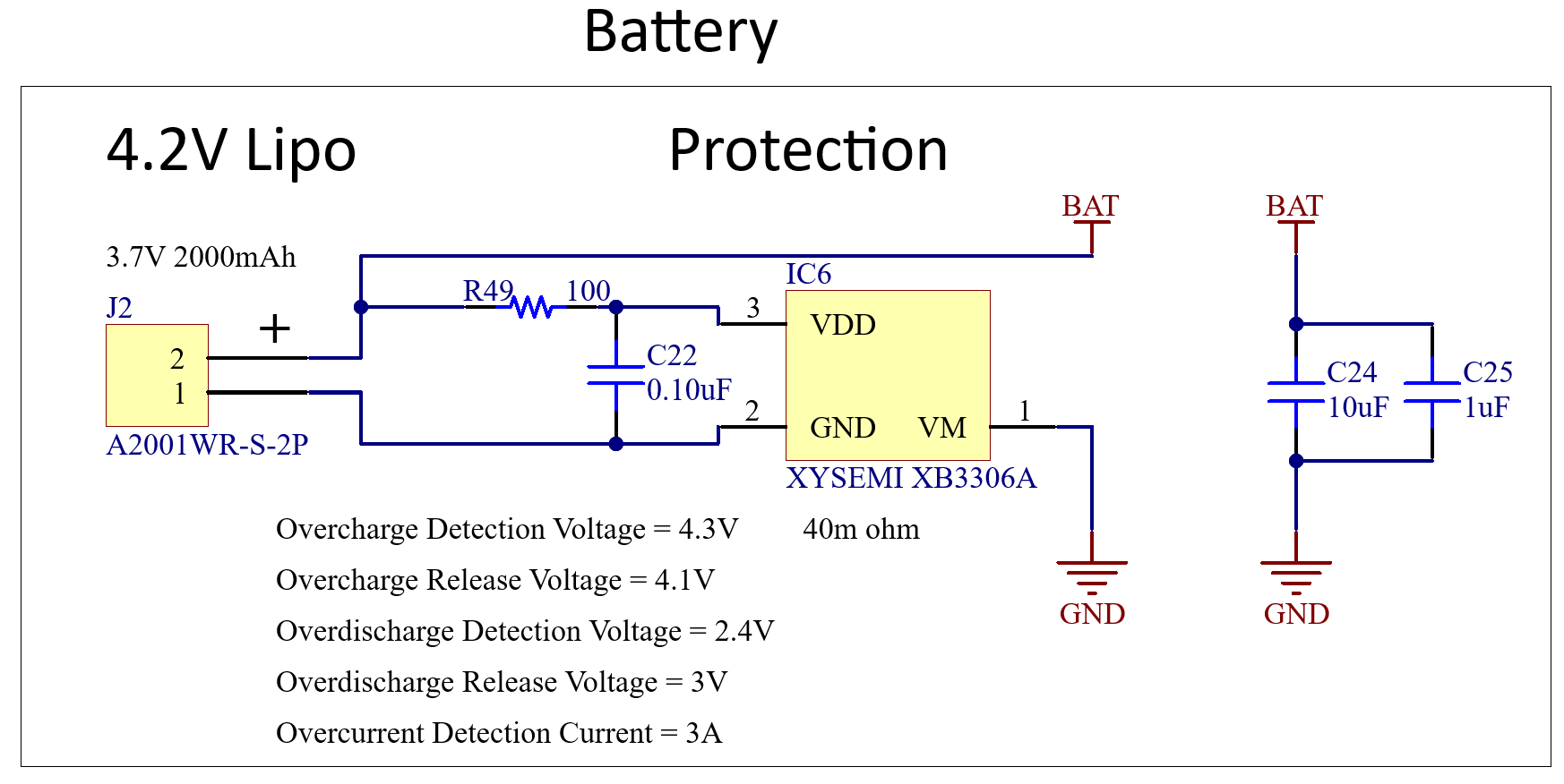
Battery is connected using a 2mm pitch JST connector.
There is a protection IC used with the following specs:
- Overcharge detection voltage: 4.3V
- Overcharge release voltage: 4.1V
- Overdischarge detection voltage: 2.4V
- Overdischarge release voltage: 3V
- Overcurrent detection voltage: 3A
Charger
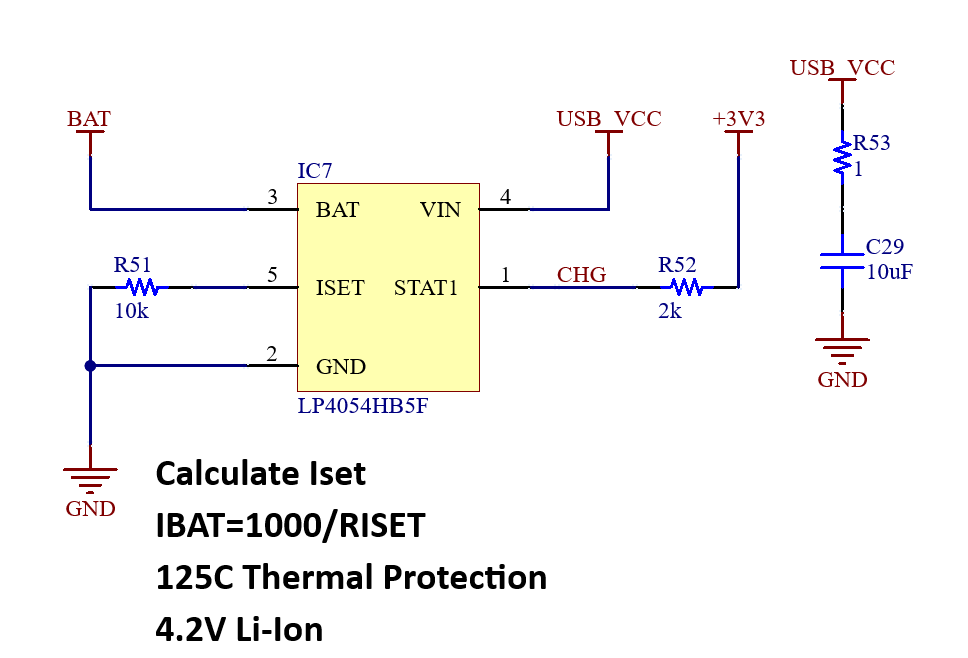
The charger IC is LP4054. It is supplied by the USB_VCC.
The charge current is specidied by R51 resistor. The default value for R51 is 10K ohm. The footprint for this resistor is 0603 size for an easy change in case it is needed. With 10K ohm, the charging current is 100mA. It can be changed using the following formula:
Charge Status
The charge status of the battery can be read using the CHG signal which is connected to IO7 of IO Expander SLG46826 (IC8).
The STAT1 pin according to the datasheet explains:
Open-Drain Charge Status Output. When the battery is charging, the STAT pin is pulled low by an internal N-channel MOSFET. When the charge cycle is completed, the pin is pulled High.
Power Switch
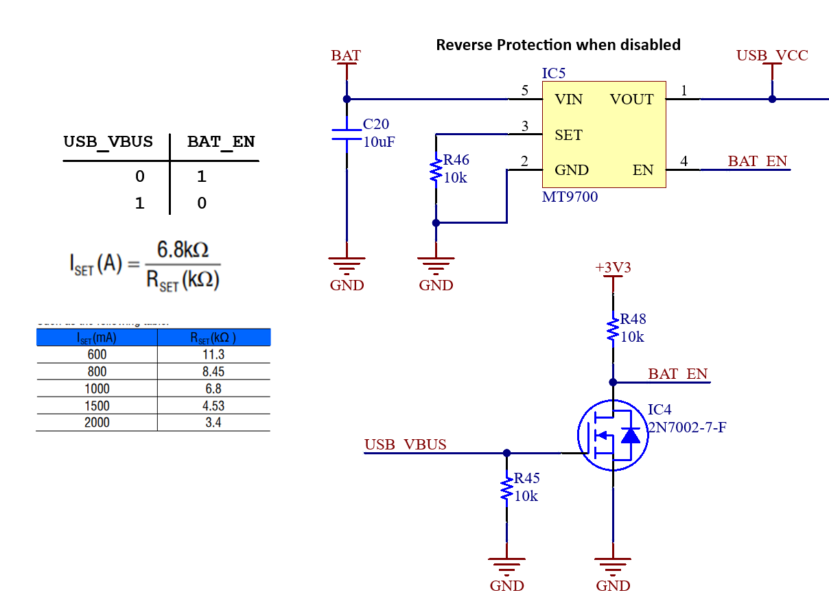
There has been a mistake. The R48 was supposed to be connected to BAT Power Source. It is fixed with a resistor patch. R48 is removed and soldered between the BAT and BAT_EN pin of IC5 (pin4 and pin 5). It will be fixed in the next release.
The circuit can source power from two power sources battery and USB-C. There is automatic switch circuit to protect the battery being powered from USB-C directly. When the circuit is powered from USB-C, the IC4 pulls BAT_EN signal low. Then IC disconnects the load which is the VOUT from VIN. There is a reverse polarity protection in IC4 (MT9700). So there is no current flowing from VOUT to VIN.